Operating clearance
Tolerance and operating clearance
The operating clearance of linear bearings is defined by the selection of shaft and housing tolerance, see tables, link.
The operating clearance of linear bearing units is defined either by the shaft or, in the case of slotted housings, is set by means of the adjustment screw.
ACHTUNG
In the case of non-rigid housings, tests must be carried out in order to achieve the required operating clearance by means of the housing and shaft tolerances.
Tolerance and operating clearance
Linear bearings, linear bearing and housing units | Designation | Tolerance | Operating clearance | |
|---|---|---|---|---|
Shaft | Bore | |||
Compact range | KH | See table, link | ||
KGHK, KTHK | h6 | ‒ | Standard | |
Light range | KN..-B, KNO..-B | h6 | H7 | Clearance-free |
Heavy duty range | KS, KSO | h6 | H7 | Clearance-free |
KGSNG, KTSG, KGSNO, KTSO, KGSC, KTFS | h6 | ‒ | Slight preload | |
KGSNS, KTSS, KGSNOS, KTSOS, KGSCS | ‒ | ‒ | Adjustable | |
Machined range | KB | See table, link | ||
KBS, KBO | ||||
KGB, KGBA, KTB, KGBO, KTBO | h6 | ‒ | See table, link | |
KGBS, KGBAS, KGBAO | ‒ | ‒ | Adjustable | |
Plain bearing range | PAB, PABO | h7 | H7 | Standard |
PAGBA, PAGBAO | h7 | ‒ | Standard | |
Mounting tolerances and operating clearance
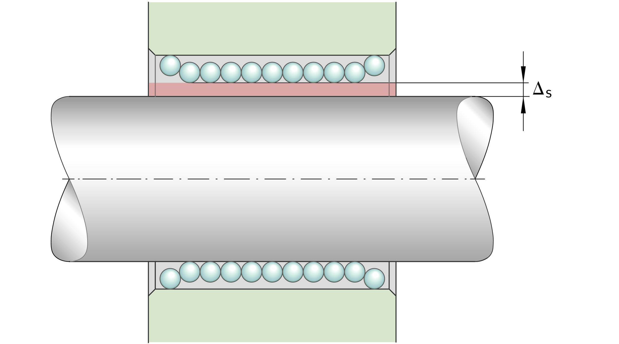
The theoretically possible operating clearance for the individual series is shown in the following tables and ➤ Figure.
Operating clearance for KH, KN..-B, KNO..-B
Mounting tolerance | Operating clearance | ||
|---|---|---|---|
Shaft | Bore | ||
h6 | H7, K7 | Normal operating clearance | Steel/ |
j5 | H6, K6 | Operating clearance smaller than normal | Steel/ |
Operating clearance for KS, KSO
Mounting tolerance | Size and operating clearance | |||||||
|---|---|---|---|---|---|---|---|---|
Shaft | Bore | 12 | 16 | 20 | 25 | 30 | 40 | 50 |
μm | μm | μm | μm | μm | μm | μm | ||
h6 | H6 | +36–8 | +34–10 | +37–12 | +34–15 | +29–20 | +33–22 | +30–25 |
h6 | H7 | +44–8 | +42–10 | +46–12 | +43–15 | +38–20 | +44–22 | +41–25 |
h6 | JS6 | +29–14,5 | +27,5–16,5 | +29–20 | +26–23 | +21–28 | +23,5–31,5 | +20,5–34,5 |
Operating clearance for KB
Mounting tolerance | Size and operating clearance | |||||||
|---|---|---|---|---|---|---|---|---|
Shaft | Bore | 12 | 16 | 20 | 25 | 30 | 40 | 50 |
μm | μm | μm | μm | μm | μm | μm | ||
h6 | H6 (H7) | +190 | +20–1 | +22–1 | +24–1 | +24–1 | +29–2 | +29–2 |
Operating clearance for KBS, KBO
Mounting tolerance | Size and operating clearance | |||||||
|---|---|---|---|---|---|---|---|---|
Shaft | Bore | 12 | 16 | 20 | 25 | 30 | 40 | 50 |
μm | μm | μm | μm | μm | μm | μm | ||
h6 | H6 | +500 | +51–1 | +60–1 | +62–1 | +62–1 | +74–2 | +74–2 |
h6 | H7 | +580 | +59–1 | +69–1 | +71–1 | +71–1 | +85–2 | +85–2 |
h6 | JS6 | +43,5–6,5 | +44,5–7,5 | +52–9 | +54–9 | +54–9 | +64,5–11,5 | +64,5–11,5 |
Operating clearance