Metal/polymer composite plain bushes, low-maintenance
Features
Low-maintenance plain bushes are used for rotary, oscillating and linear motion. These plain bearings are bearings for very small radial or axial design envelopes. They are rolled from a cut section of strip and have a butt joint over the entire width of the bearing.
ACHTUNG
If the plain bushes are to be used in the aerospace sector or in the food or pharmaceuticals industry, please contact the Schaeffler engineering service.
Low-maintenance plain bearing material
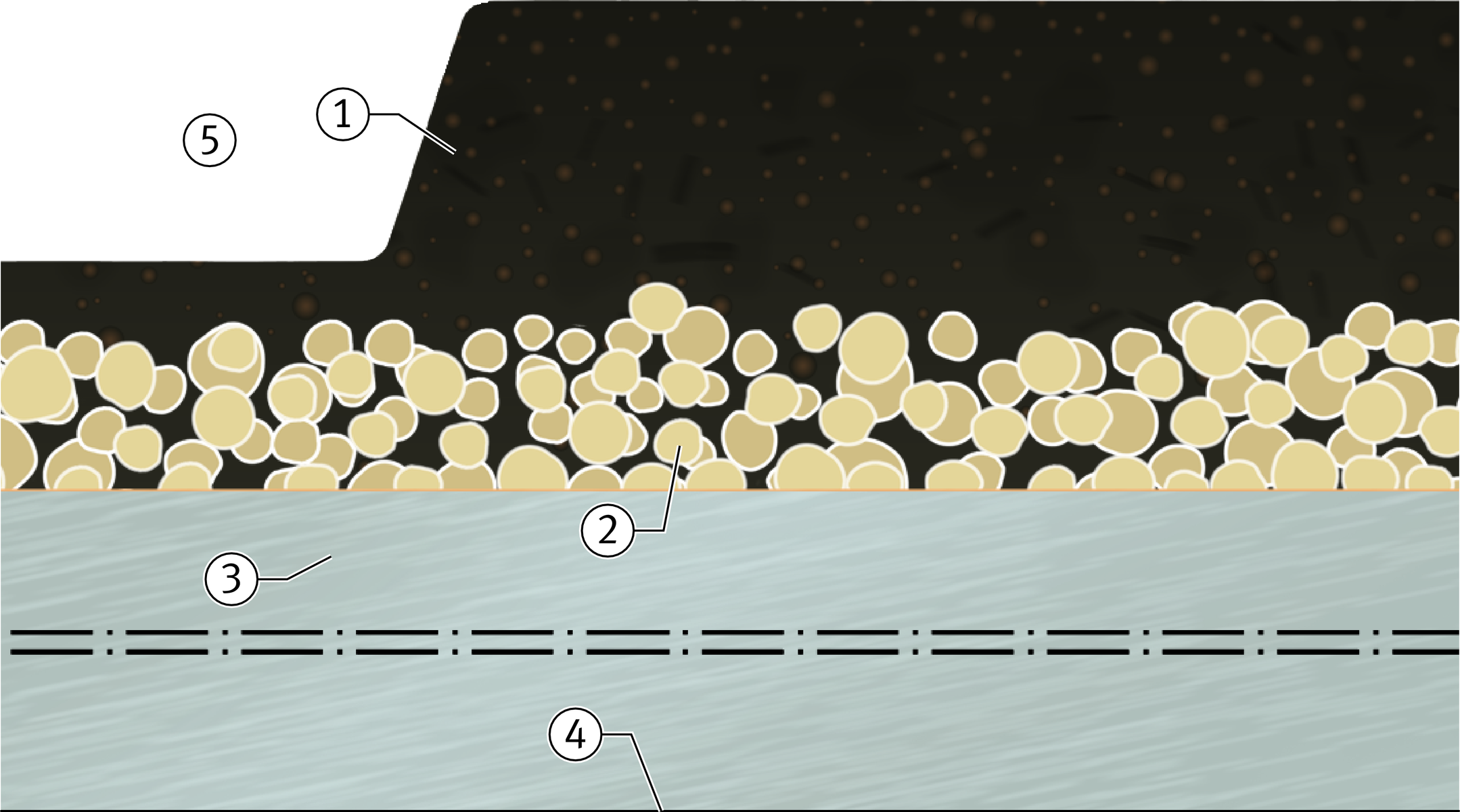
For low-maintenance metal/polymer composite plain bearings from Schaeffler, the sliding material E50 is used. The basis of the sliding layer is polyoxymethylene POM.
In the three-layered material, the steel backing has a sintered porous tin/bronze intermediate layer whose pores are filled with the superimposed sliding layer, see table and ➤ Figure.
Sliding and intermediate layer E50
Chemical element | Proportion of mass | Layer thickness | ||
|---|---|---|---|---|
w | ||||
% | mm | |||
Intermediate layer | Sliding | Intermediate layer | Sliding | |
Polyoxymethylene POM | ‒ | 99,6 – 99,8 | 0,15 – 0,5 | 0,2 – 0,5 |
Fillers | max. 0,95 | max. 0,4 | ||
Tin Sn | 10 – 12 | ‒ | ||
Copper Cu | Balance | ‒ | ||
Low-maintenance plain bearing material E50


Surface protection
As standard, the plain bearing has a tin layer as surface protection.
Resistance of the plain bearing material
The resistance of the material E50 depends on the chemical characteristics of the individual layers:
- The material E50 is resistant to many greases.
- The tin-plated steel surface gives adequate protection against corrosion in most cases.
ACHTUNG
The material E50 is not resistant to acidic media (pH < 5) and alkaline media (pH > 9).
Technical data for E50
The sliding layer E50 is a low-maintenance, low-wear material with good damping characteristics and long relubrication intervals. It can be used for rotary and oscillating motion and for long stroke linear motion, is only slightly sensitive to edge loads and is insensitive to shocks.
The low-maintenance plain bearing material E50 has the following mechanical and physical characteristics, see table.
Characteristics of E50
Characteristics | Load | ||
|---|---|---|---|
Maximum pv value | pv | 3 N/mm2 · m/s | |
Permissible specific | Static | pmax | 140 N/mm2 |
Rotary, oscillating | 70 N/mm2 | ||
Permissible sliding velocity | vmax | 2,5 m/s | |
Permissible operating temperature | ϑ | –40 °C to +110 °C | |
Coefficient | Steel backing | αSt | 11 · 10–6 K–1 |
Coefficient | Steel backing | λSt | <4 Wm–1K–1 |
Coefficient of friction | μ | 0,02 to 0,2 | |
Sealing
The plain bearings are not sealed, but can be protected against the ingress of contamination and moisture by the use of external seals.
Lubrication
The low-maintenance plan bearing material E50 has lubrication pockets. The lubrication pockets retain the lubricant, which means that an initial lubrication is sufficient in most cases.
The operating life increases if relubrication is carried out regularly.
Plain bearing bushes made from E50 have a lubrication hole.
Greases
Low-maintenance plain bearings made from E50 must be lubricated using suitable grease or oil.
Lithium soap greases with a mineral oil base are highly suitable.
Grease additives such as molybdenum disulphide, zinc sulphide or other solid lubricants are unfavourable since they increase wear. Greases may contain max. 5% MoS2.
Operating temperature
The permissible operating temperature for low-maintenance plain bearings is between –40 °C and +110 °C.
Suffixes
Suffixes for available designs: see table.
Available designs
Suffix | Description | Design |
|---|---|---|
E50 | Low-maintenance sliding layer, | Standard |
Design and safety guidelines
In addition to the design and safety guidelines described here, the following guidelines in the Technical principles must also be observed:
- theoretical bearing clearance of metal/polymer composite plain bushes
- design of bearing arrangements
- recommended mounting tolerances
- misalignment of plain bushes and edge loading of metal/polymer composite plain bushes
- pressing in of bushes.
ACHTUNG
Plain bushes should not be used for movement involving spatial motion. Any skewing of the shaft will reduce the operating life.
Friction
The characteristic coefficients of friction, calculation of the bearing frictional torque and the typical wear characteristics are given in the chapter Technical principles.
Dimensioning and rating life
The dimensioning of plain bushes is summarised in the chapter Technical principles.
Depending on whether the bearing is subjected to dynamic or static load, the following must be checked:
- static load safety factor S0
- maximum permissible specific bearing load p
- maximum permissible sliding velocity v
- maximum specific frictional energy pv.
ACHTUNG
The rating life can be calculated if the range of validity is observed.
Design of mating surfaces
The shaft and mating surface of the bearing arrangement must be produced in accordance with the following specifications.
The shafts or parts of the mating surfaces should be chamfered and all sharp edges should be rounded. This allows easier mounting and prevents damage to the sliding layer.
Measures
The mating surface should always be wider than the bearing to prevent the formation of steps in the sliding layer.
The optimum operating life will be achieved with a roughness depth of the mating surface of Rz 2 to Rz 3:
- with lubrication of the sliding layer E50.
ACHTUNG
Very small roughness values do not have a beneficial effect on the operating life, but larger roughness values reduce it considerably.
Surface quality
Ground or drawn surfaces are preferable as a mating surface. Surfaces that have been precision turned or rolled by precision turning, even with Rz 2 to Rz 3, can cause greater wear since helical manufacturing grooves are created by precision turning.
Spheroidal graphite cast iron GGG has an open surface structure and should therefore be ground to Rz 2 or better.
The direction of rotation of cast shafts in the application should be the same as that of the grinding wheel during machining, since increased wear should be anticipated if rotation is in the opposing direction, ➤ Figure.
Grinding of a cast shaft
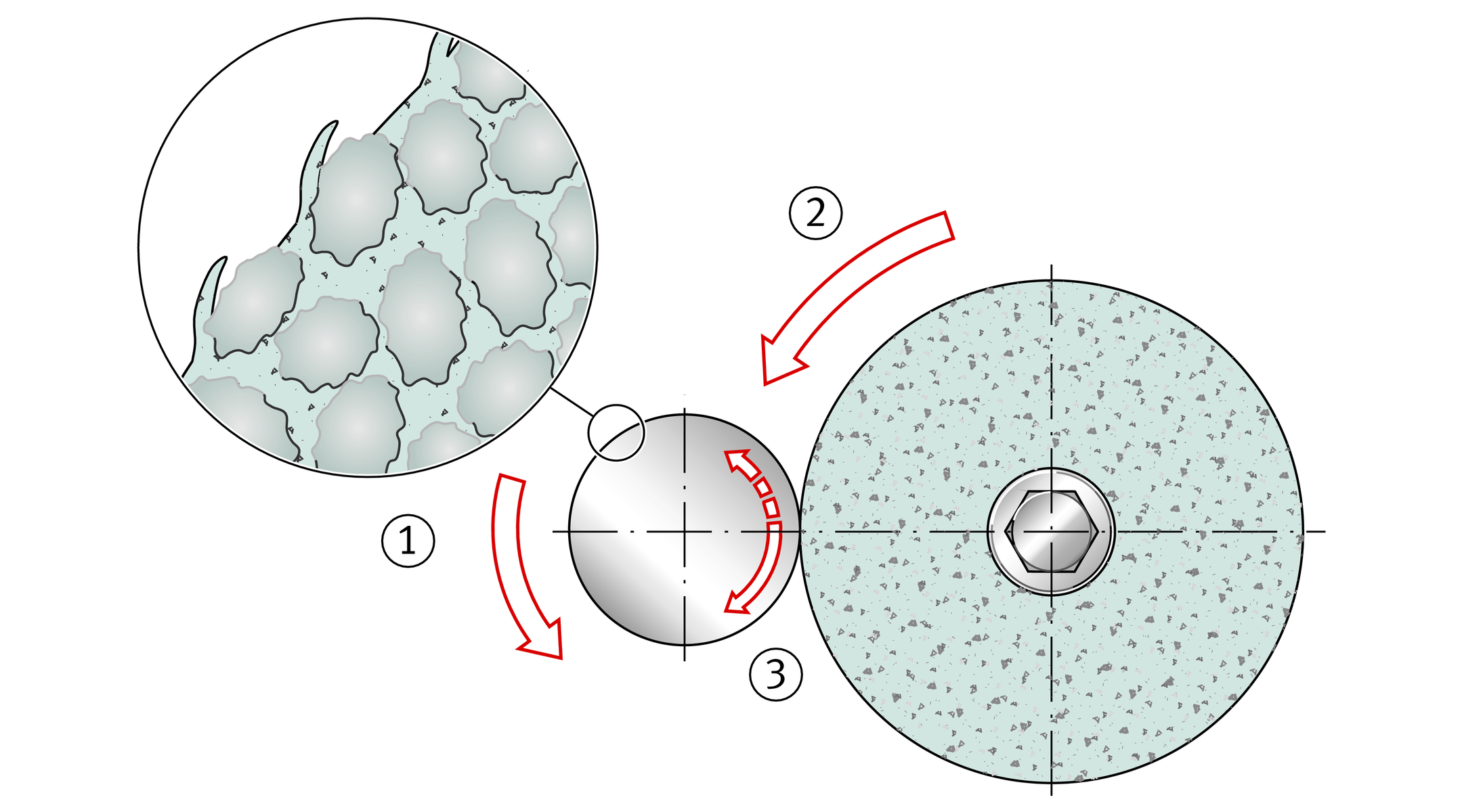
in the application ·
during grinding
Heat dissipation
Correct and sufficient heat dissipation must be ensured:
- If media-lubricated operation is present, the heat is dissipated predominantly via the fluid lubricant.
- In the case of low-maintenance plain bearings, the heat is dissipated via the housing and shaft.
Protection against corrosion
Corrosion of the mating surface is prevented by sealing or the use of corrosion-resistant steel. Alternatively, suitable surface treatments may be carried out.
In the case of the sliding layer E50, the lubricant gives additional protection against corrosion.
Fretting corrosion
Due to the tin coating applied as standard, fretting corrosion between the steel backing of the plain bearing material and the housing occurs only rarely. In such cases, electroplated protective coatings can be used to achieve a delaying effect.
Electrochemical contact corrosion
In unfavourable conditions, electrical cells (local elements) can be formed that reduce the operating life through corrosion of the steel. This should be checked at the design stage and clarified by means of tests. In case of doubt, please consult the Schaeffler engineering service.
Machining of plain bearings
Metal/polymer composite plain bearings can be machined by either cutting or non-cutting methods, such as shortening, drilling or bending.
The procedure is as follows:
- Separate the plain bearings starting from the sliding layer side, since the burr formed in cutting will impair the running surface
- Clean the bearing elements thoroughly.
- Protect any bright steel surfaces such as cut edges against corrosion by means of oil or electroplated protective coatings.
ACHTUNG
In electroplating with high current densities or or long coating times, the sliding layers should be masked to prevent deposits.
The machining temperature must not exceed +110 °C in the case of the sliding layer E50.
Alternative joining methods
If the press fit of the bush is not sufficient, the bush can be secured by additional adhesive bonding.
ACHTUNG
The running-in or sliding surface must always be kept free of adhesive.
If adhesive is used, the adhesive manufacturer must always be consulted, particularly on the selection of adhesives, preparation of the surface, hardening, strength, temperature range and elongation behaviour.
Tables of deviations and wall thicknesses
The deviations for the bushes are defined in ISO 3547.
Deviations
of outside diameter
The deviations for the outside diameter Do conform to ISO 3547-1, Table 7, see table.
Deviations
Tolerances in mm
Do | E50 | ||||
|---|---|---|---|---|---|
Deviation | |||||
mm | upper | lower | |||
| Do ≦ | 10 | +0,055 | +0,025 | |
10 | < | Do ≦ | 18 | +0,065 | +0,030 |
18 | < | Do ≦ | 30 | +0,075 | +0,035 |
30 | < | Do ≦ | 50 | +0,085 | +0,045 |
50 | < | Do ≦ | 80 | +0,100 | +0,055 |
80 | < | Do ≦ | 120 | +0,120 | +0,070 |
120 | < | Do ≦ | 180 | +0,170 | +0,100 |
180 | < | Do ≦ | 305 | +0,255 | +0,125 |
Wall thickness
for sliding layer E50
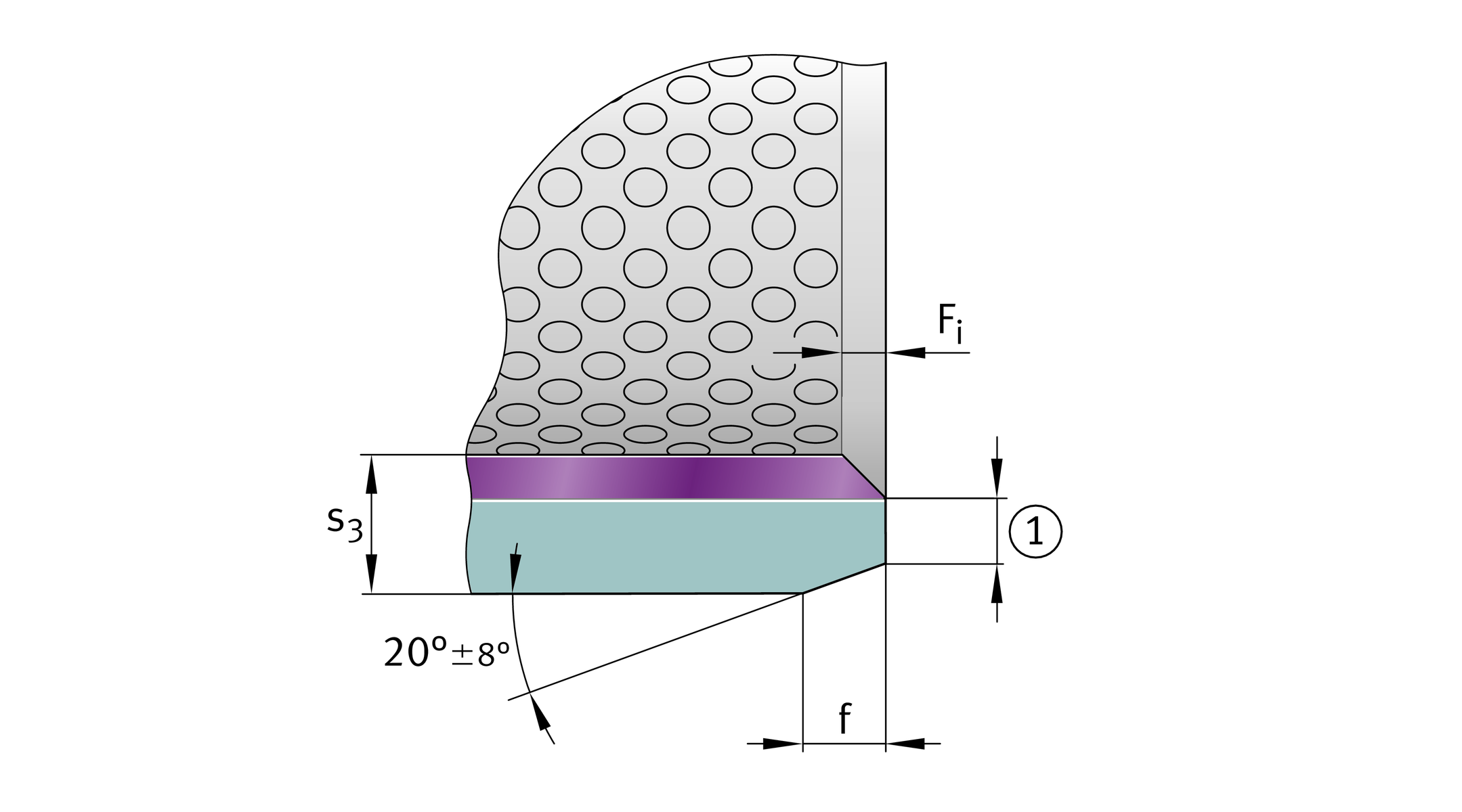
The nominal dimensions and limit deviations for the wall thickness s3 of bushes with the sliding layer E50 for inside diameter Di conform to ISO 3547-1, Table 5, Series D, see table.
Wall thickness
Tolerances in mm
Di | s3 | E50 | ||||
|---|---|---|---|---|---|---|
Deviation | ||||||
mm | mm | upper | lower | |||
8 | ≦ | Di < | 20 | 1 | –0,020 | –0,045 |
20 | ≦ | Di < | 28 | 1,5 | –0,025 | –0,055 |
28 | ≦ | Di < | 45 | 2 | –0,030 | –0,065 |
45 | ≦ | Di | 2,5 | –0,040 | –0,085 | |
Chamfers and chamfer tolerances
The tolerances and dimensions of the outer chamfer f and the inner edge break Fi for bushes of metric sizes conform to ISO 3547-1.
Chamfer deformation due to round bending is permissible.
Outer chamfer and inner edge break