Design of bearing arrangements
Requirements for the adjacent construction
The running accuracy of the linear guidance system is essentially dependent on the straightness, accuracy and rigidity of the mounting surfaces.
The higher the requirements for accuracy and smooth running of a track roller guidance system, the more attention must be paid to the geometrical and positional accuracy of the adjacent construction. The adjacent surfaces should be flat and have parallel faces.
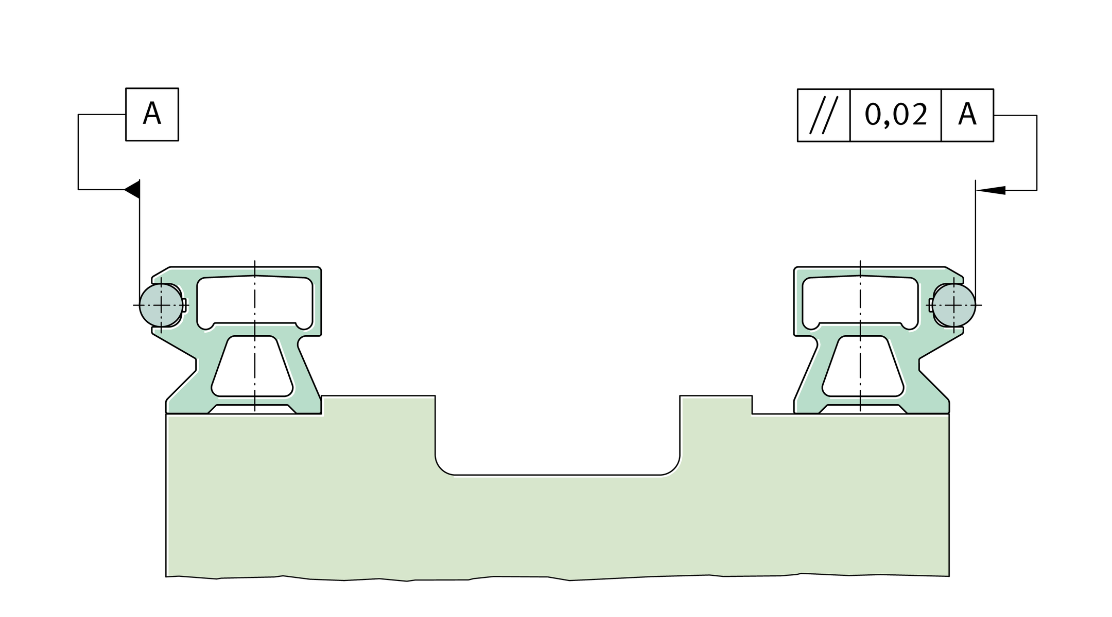
For two guideways, we recommend a parallelism according to ➤ Figure.
Parallelism of guideways
Shaft creep
Under unfavourable conditions, shaft creep of a few millimetres may occur in isolated cases. This creep may occur mainly in applications with high accelerations in conjunction with high alternating loads and guideways that are not completely supported. It may also be caused by an adjacent construction that is too soft.
In such cases, shaft creep can be prevented by the use of end plates ANS.LFS. They can be supplied already mounted.
Displacement force
The displacement force is dependent on the preload, the lubrication and the particular application. It is therefore not possible to make generally valid statements.
Location of carriages and guideways
If lateral loads are present, it is recommended that the guideways and carriages should be located against locating surfaces. In the case of guideways comprising multiple sections joined together, it is recommended that the guideways should be aligned by means of the shaft. If necessary, the shafts should be located on the adjacent construction by means of dowels.
If two guideways are arranged in parallel, the first guideway should be clamped against a stop, ➤ Figure. The second guideway should then be aligned accordingly. Any gaps between the guideway and the adjacent construction should be filled with synthetic resin.
Track roller guidance systems in accordance with customer specifications
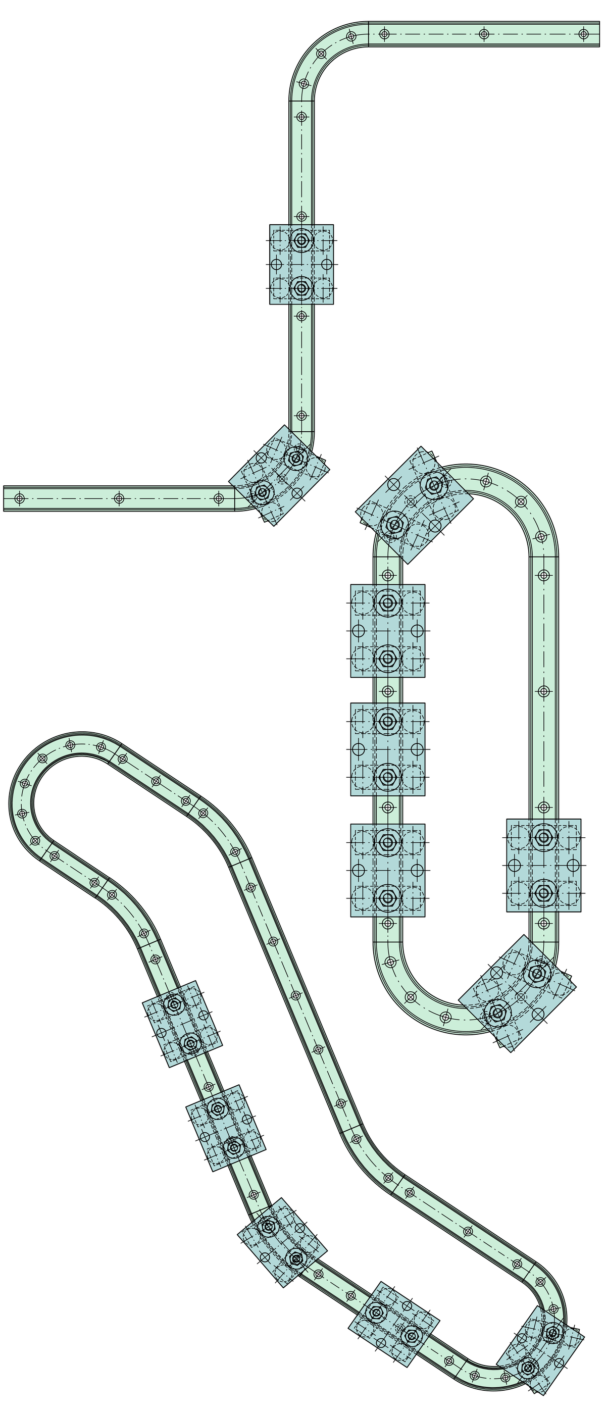
The INA track roller guidance systems with curved guideway elements can be used to achieve an extremely wide variety of applications, ➤ Figure and ➤ Figure.
If the arrangement required cannot be represented using the standard ordering designation, a customer drawing must be submitted with the enquiry.
For arrangements with curved guideway elements, it is recommended that the guideway connectors VBS should be used at the joints. This gives considerably easier mounting.
ACHTUNG
Standard oval tracks are always supplied with guideway connectors VBS.
Arrangement according
to customer requirements
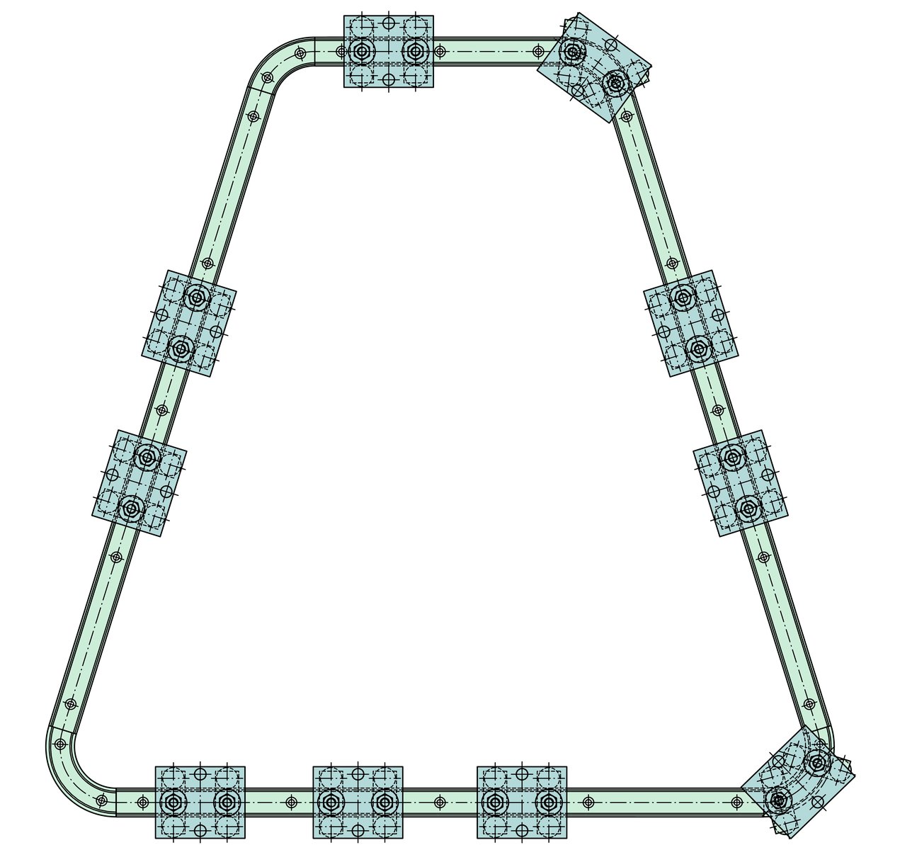
Closed and open applications with guidance systems including curved guideway elements
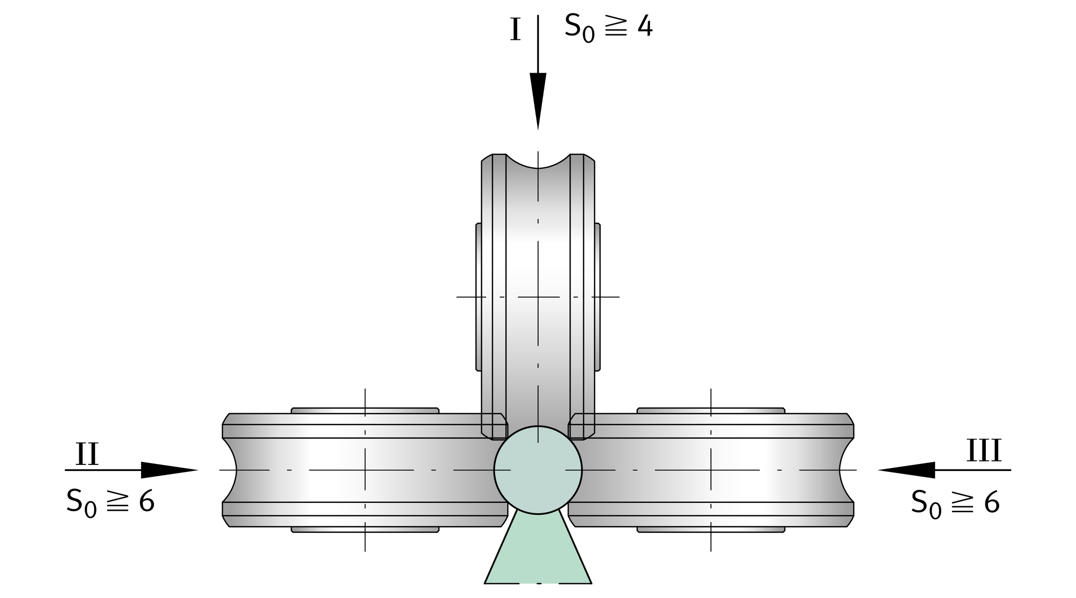
Possible combinations of profiled track rollers with guideways
| Shaft and support rail units | |||
|---|---|---|---|---|
| ||||
Shaft | TSNW, TSNW..-G4, -G5 | |||
Fixing screw | Load case, ➤ Figure | |||
I | II | III | ||
mm | ||||
12 | DIN ISO 4 762 | ■ | ‒ | ‒ |
DIN 7 984 | ■ | ■ | ■ | |
16 | DIN ISO 4 762 | ■ | ‒ | ‒ |
DIN 7 984 | ■ | ‒ | ‒ | |
20 | DIN ISO 4 762 | ■ | ‒ | ‒ |
DIN 7 984 | ■ | ‒ | ‒ | |
25 | DIN ISO 4 762 | ■ | ■ | ■ |
DIN 7 984 | ■ | ■ | ■ | |
30 | DIN ISO 4 762 | ■ | ‒ | ‒ |
DIN 7 984 | ■ | ■ | ■ | |
40 | DIN ISO 4 762 | ■ | ■ | ■ |
DIN 7 984 | ■ | ■ | ■ | |
50 | DIN ISO 4 762 | ■ | ■ | ■ |
DIN 7 984 | ■ | ■ | ■ | |

■
Combination possible if the rail is located using the stated screw.
–
Please contact us.
| Shaft and support rail units | ||||||||
|---|---|---|---|---|---|---|---|---|---|
|
| ||||||||
Shaft | TSUW | TSSW | |||||||
tmax | bmax | Load case, ➤ Figure | tmax | Load case, ➤ Figure | |||||
I | II | III | I | II | III | ||||
mm | mm | mm | mm | ||||||
12 | 5 | 5 | ● | ❍** | ‒ | ‒ | ‒ | ‒ | |
16 | ‒ | ‒ | ● | ‒ | ‒ | ‒ | ‒ | ‒ | ‒ |
20 | ‒ | ‒ | ● | ‒ | ‒ | ‒ | ● | ‒ | ‒ |
25 | 10 | 12 | ● | ● | ❍ | 36 | ● | ● | ● |
30 | 12 | 16 | ● | ● | ❍ | 42 | ● | ● | ● |
40 | 10 | ‒ | ● | ● | ❍ | 50 | ● | ● | ● |
50 | 13 | ‒ | ● | ● | ❍ | 70 | ● | ● | ● |


●
Combination possible.
❍
Combination possible if t ≦ tmax and b ≦ bmax.
–
Please contact us.
**With AB.W: tmax = 2,5.
| Shaft and support rail units | ||
|---|---|---|---|
| |||
Shaft diameter | TSMW | ||
Load case, ➤ Figure | |||
I | II | III | |
mm | |||
12 | ‒ | ‒ | ‒ |
16 | ‒ | ‒ | ‒ |
20 | ● | ‒ | ‒ |
25 | ● | ● | ● |
30 | ● | ● | ● |
40 | ‒ | ‒ | ‒ |
50 | ‒ | ‒ | ‒ |

●
Combination possible.
–
Please contact us.
ACHTUNG
For the combination, take account of:
- the static load safety factor S0
- the load cases
- a shaft hardness of 670 HV.
Load cases I, II and III